Key Takeaway
The working principle of a multimeter involves converting electrical signals like voltage, current, and resistance into measurable readings.
The multimeter uses internal sensors to detect changes in the electrical properties of the circuit. These readings are then displayed as numerical values on the screen or scale, depending on whether it’s an analog or digital multimeter.
Understanding the Core Working Mechanism of Multimeters
Multimeters operate by using an internal circuit that detects and quantifies electrical signals. When you measure voltage, current, or resistance, the multimeter processes the input signal and displays the result on its screen.
In voltage measurement, the multimeter acts as a high-impedance device to avoid interfering with the circuit. For current, it connects in series to measure the flow of electrons. Resistance measurement involves passing a small current through the component and calculating its opposition.
Understanding the internal workings of a multimeter helps you use it more effectively and troubleshoot any issues with its operation. This knowledge is fundamental for maximizing its utility in various applications.
How Multimeters Measure Voltage, Current, and Resistance
Multimeters are versatile tools designed to measure three key electrical properties: voltage, current, and resistance. Each of these measurements is made using different internal components and techniques, and understanding how multimeters perform these tasks is crucial for accurate testing and troubleshooting.
Measuring Voltage: To measure voltage, a multimeter is connected across two points of a circuit. The multimeter then calculates the electrical potential difference between these two points. For DC voltage (DCV mode), the multimeter measures the constant, unidirectional voltage in the circuit, such as that from a battery. In AC voltage (ACV mode), the multimeter measures the alternating voltage, which fluctuates in direction over time. The multimeter uses a voltage divider network and amplifies the signal to display a readable value.
Measuring Current: Measuring current requires the multimeter to be placed in series with the circuit. Current is the flow of electrons, and to measure it, the multimeter needs to become part of the current path. The multimeter’s internal shunt resistor generates a small voltage drop proportional to the current flowing through it, which the device then measures to display the current in amperes.
Measuring Resistance: Resistance is measured by sending a small current through the circuit and calculating how much it is opposed by the components in the path. The multimeter uses an internal battery to generate the current, then measures the voltage drop across the component or circuit. Using Ohm’s law (V = I × R), it calculates the resistance (R) by dividing the voltage by the current.
By understanding how multimeters measure these properties, users can select the correct settings and use the tool effectively for diagnosing electrical systems.
You May Like to Read
Role of Internal Components in Multimeter Functionality
1. The Power Supply
The power supply of a multimeter provides the necessary voltage for the operation of the internal circuitry. It typically consists of a battery or rechargeable power source, which energizes the components inside the multimeter, ensuring proper operation when performing measurements.
2. Analog-to-Digital Converter (ADC)
The ADC is a key component in modern digital multimeters. It converts the analog signals from the circuit under test into digital signals, which the microprocessor can process and display on the screen. This conversion ensures that voltage, current, and resistance readings are presented in a format that is easy to interpret.
3. The Microprocessor
The microprocessor is at the heart of a digital multimeter. It receives the signals from the ADC, processes them, and then sends the data to the display. The microprocessor determines what measurement function (voltage, current, resistance) is active and controls the accuracy of the reading by calculating the appropriate values based on the input signal.
4. Input Protection Circuitry
Safety is paramount when using a multimeter, especially for high-voltage or high-current measurements. The input protection circuitry ensures that excess voltage or current does not damage the internal components. It acts as a safeguard to prevent the multimeter from being overloaded or subjected to voltages beyond its rated capacity.
5. Display
The display shows the measured values, and it can either be analog or digital. In digital multimeters, the display is usually an LCD screen that provides a clear reading of the voltage, current, or resistance. The clarity of the display is crucial for quick and accurate interpretation.
Differences in Working Principles of Analog and Digital Multimeters
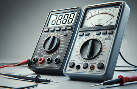
Analog and digital multimeters (DMMs) are both commonly used for measuring electrical parameters such as voltage, current, and resistance. However, their working principles differ significantly. An analog multimeter uses a moving needle or pointer on a graduated scale to indicate the value of the electrical parameter being measured. This type of multimeter operates on a moving coil mechanism where the needle deflects in response to the current or voltage passing through the meter, providing a continuous, analog display. While analog multimeters offer simplicity, they can sometimes be harder to read, especially for measurements with small changes.
In contrast, digital multimeters provide numerical readings on a digital display. These meters use an electronic circuit that converts the measured electrical signal into a digital format, displaying the result on an LED or LCD screen. Digital multimeters offer greater accuracy, higher resolution, and ease of use compared to analog models. Since they display exact numerical values, users can read measurements with greater precision, reducing the chances of error when interpreting the results.
One of the advantages of digital multimeters is their ability to store and process data, allowing them to display more complex information like frequency, capacitance, and temperature, in addition to the basic parameters such as voltage and current. Many DMMs also come with auto-ranging features, automatically adjusting the measurement range to suit the voltage or current being tested. While analog meters can be more affordable and simpler for basic tasks, digital multimeters are generally preferred for their accuracy, versatility, and ease of interpretation.
The choice between analog and digital multimeters largely depends on the specific needs of the user. Analog meters are often used for quick, approximate measurements in low-tech environments, while digital meters are better suited for precise, high-tech applications where accuracy is paramount.
Practical Applications of Multimeter Principles
The principles behind multimeters have wide-ranging applications across various industries, from residential to industrial settings. At its core, a multimeter measures voltage, current, and resistance, all fundamental properties for understanding and troubleshooting electrical circuits. In practice, these principles allow technicians and engineers to diagnose electrical issues, verify the functionality of components, and ensure that circuits are safe to operate.
For example, a technician in a residential setting may use a multimeter to test the voltage in an electrical outlet, check the resistance of a heating element, or measure the current in a lighting circuit. In industrial environments, the same principles are applied to more complex systems such as motors, power distribution systems, and control circuits. By understanding and applying the fundamental principles of multimeter operation, professionals can troubleshoot, repair, and optimize a wide range of electrical systems.
Conclusion
In conclusion, the working principle of a multimeter revolves around its ability to detect and display electrical parameters such as voltage, current, and resistance. This is achieved by using an internal circuit that interacts with the probes connected to the component or circuit being tested. Whether it’s an analog or digital multimeter, the principle remains consistent: interpreting electrical signals and providing a readable output.
Understanding this principle is key to using a multimeter effectively and safely. It empowers users to handle troubleshooting, repairs, and testing with confidence, ensuring they get accurate and reliable measurements.