Key Takeaway
The principle of a voltmeter is based on measuring the potential difference between two points in a circuit. It works by connecting in parallel with the component or section of the circuit being tested.
The voltmeter measures the voltage across these two points and displays it on a scale or digital readout.
Fundamental Principles Behind Voltmeter Operation
A voltmeter measures the potential difference between two points in an electrical circuit. It operates by introducing minimal current to the circuit, ensuring accurate readings without altering the circuit’s functionality.
Voltmeters are designed with high internal resistance to prevent them from drawing significant current. They are connected in parallel to the circuit for measuring voltage. For instance, to test a power supply, the voltmeter probes are placed across the supply terminals.
Understanding the principles behind voltmeter operation ensures proper usage, leading to accurate and reliable measurements in various electrical applications.
How Voltmeters Measure Electrical Potential Difference
A voltmeter is a specific type of measurement tool designed to measure the electrical potential difference, or voltage, between two points in an electrical circuit. Voltage is the driving force that causes electric charge to flow through a conductor, and measuring it is essential for understanding how electrical circuits are functioning.
To measure voltage, a voltmeter is connected across two points of the circuit—this is known as being connected in parallel. The voltmeter measures the difference in electrical potential between these two points, and it does so by detecting the amount of energy required to move charge from one point to the other. This is typically represented in volts (V).
In a typical digital multimeter, the voltage is measured by placing the multimeter probes across the circuit, with one probe placed at each measurement point. The voltmeter then uses an internal circuit, which may include resistors and voltage dividers, to calculate the potential difference. In DC circuits, this measurement will be steady, reflecting the direct flow of electrical energy, while in AC circuits, the voltmeter will measure the alternating fluctuations of the voltage.
One of the primary advantages of using a voltmeter is that it does not require the circuit to be interrupted, meaning it can be measured without breaking the flow of electricity. This is particularly important in live circuits where interruption could cause safety hazards. Voltmeters, therefore, provide an essential and non-invasive method for monitoring the voltage in electrical systems and troubleshooting potential issues.
You May Like to Read
Types of Voltmeters and Their Working Principles
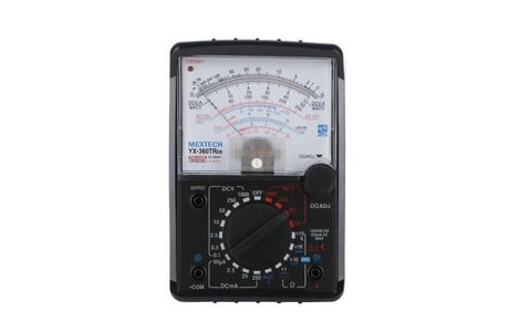
1. Analog Voltmeters
Analog voltmeters use a moving coil mechanism to measure voltage.
Working Principle:
The coil in the meter is placed in a magnetic field created by a permanent magnet.
When the circuit is powered, a current flows through the coil.
This current creates a force that moves the needle along the scale, indicating the voltage.
2. Digital Voltmeters
Digital voltmeters (DVMs) use digital circuits to measure the voltage.
Working Principle:
The input voltage is passed through an input signal conditioning circuit.
This circuit ensures that the voltage is suitable for measurement by the ADC.
The ADC samples the voltage and converts it into a digital value.
The microprocessor processes this value and displays the result on the LCD or LED screen.
3. High-Voltage Voltmeters
High-voltage voltmeters are designed specifically to handle high-voltage measurements, typically over 1000 volts. T
Working Principle:
The internal circuitry is designed to handle the high voltage without causing damage or posing a safety risk.
These voltmeters use precision resistors and voltage dividers to reduce the high voltage to a level that can be safely measured by the meter.
4. Digital Panel Meters (DPM)
Digital Panel Meters are specialized voltmeters that are often installed in electrical panels for continuous monitoring of voltage in industrial or commercial settings. T
Working Principle:
Digital panel meters function similarly to other digital voltmeters.
The key difference is that they are designed to be installed permanently in circuits for continuous monitoring.
These meters typically feature large displays for easy reading and can be connected to systems for remote monitoring.
Differences Between Analog and Digital Voltmeters
Analog and digital voltmeters are essential tools used for measuring voltage in electrical circuits, but they differ significantly in their design and operation. Analog voltmeters rely on a moving coil meter and a needle to indicate the voltage level on a scale. The needle moves according to the amount of voltage in the circuit, providing a continuous reading. While analog voltmeters are simple and relatively inexpensive, they have some limitations, such as lower precision, difficulty in reading small or fluctuating measurements, and less accuracy at higher voltages.
On the other hand, digital voltmeters (DVMs) provide voltage readings in a numerical format on an LED or LCD display. The digital format makes readings more precise and easier to interpret, especially when dealing with low or fluctuating voltages. Digital voltmeters also offer greater resolution, allowing them to measure voltage with higher accuracy. Many modern digital voltmeters come with features like auto-ranging, which automatically adjusts the measurement range depending on the voltage being tested. This feature adds to their ease of use, particularly for beginners or individuals unfamiliar with electrical measurements.
The primary advantage of digital voltmeters over analog ones is their accuracy and ease of use. Digital voltmeters are better for precise measurements and applications where high accuracy is crucial, such as in circuit design, troubleshooting, and research. Analog voltmeters, while less precise, are often still used in simpler, less demanding applications or for those who prefer an analog reading. The choice between analog and digital voltmeters depends largely on the specific needs of the user, including the required precision and complexity of the measurements.
Common Applications of Voltmeters in Electrical Testing
Voltmeters, a crucial tool for measuring electrical potential difference, have widespread applications in both residential and industrial settings. Commonly, voltmeters are used to check the voltage levels in electrical circuits to ensure that the voltage matches the specified requirements. For example, electricians use voltmeters to measure the voltage output of transformers, check the condition of electrical appliances, or verify that a power source is operating within its safe voltage range.
Voltmeters also play an essential role in troubleshooting electrical issues. For instance, when a device or circuit is malfunctioning, measuring the voltage at different points in the circuit helps identify where the problem lies. If a voltage drop is detected in a particular section of the circuit, it can indicate a fault, such as a short circuit or a loose connection. Overall, voltmeters are fundamental in ensuring the safety, efficiency, and proper operation of electrical systems, particularly when performing routine checks, repairs, or installations.
Conclusion
In conclusion, a voltmeter operates on the principle of measuring the potential difference between two points in a circuit. By connecting the voltmeter in parallel, it detects the voltage without significantly affecting the circuit’s operation. The internal resistance of a voltmeter is kept high to minimize current draw.
This fundamental principle enables voltmeters to be invaluable tools in diagnosing and troubleshooting electrical systems, ensuring precise and reliable measurements.