Key Takeaway
The formula for calculating the characteristics of a relay coil can be expressed using Ohm’s Law, which is = × V=I×R. Here, “V” stands for the voltage applied across the relay coil, “I” indicates the current flowing through the coil, and “R” represents the coil’s resistance. This formula helps you understand how much current will flow through the coil when a certain voltage is applied, considering its resistance. It’s crucial for designing circuits that use relay coils effectively and safely.
Understanding Relay Coil Specifications
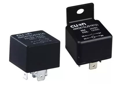
Relay coils are critical components that enable the functioning of relays by generating the necessary electromagnetic force to operate the relay contacts. To design and use relay coils effectively, it’s essential to understand their specifications. Key parameters include coil voltage, resistance, inductance, and the current required to activate the relay. Coil voltage is the electrical potential needed to energize the coil, while coil resistance determines how much current flows through it. Inductance measures the coil’s ability to store energy in a magnetic field, impacting the relay’s response time and efficiency.

Basic Formula for Calculating Relay Coil Parameters
To calculate the parameters of a relay coil, we use several fundamental electrical formulas. The primary formula involves Ohm’s Law, which is:
V=I×RV = I times RV=I×R
where:
• VVV is the voltage,
• III is the current,
• RRR is the resistance.
This formula is crucial for determining the appropriate coil resistance to ensure the relay operates correctly. For instance, if a relay requires a voltage of 12V and a current of 0.1A to function, the resistance can be calculated as R=VI=12V0.1A=120ΩR = frac{V}{I} = frac{12V}{0.1A} = 120 OmegaR=IV=0.1A12V=120Ω.
Another essential formula is for calculating the inductance (LLL) of the coil, which is:
L=N2⋅μ⋅AlL = frac{N^2 cdot mu cdot A}{l}L=lN2⋅μ⋅A
where:
• NNN is the number of turns of the coil,
• μmuμ is the permeability of the core material,
• AAA is the cross-sectional area of the coil,
• lll is the length of the coil.
For example, if a coil has 200 turns, a core material permeability (μmuμ) of 4×10⁻⁷ H/m4 times 10^{-7} , H/m4×10−7H/m, a cross-sectional area (AAA) of 0.01 m20.01 , m^20.01m2, and a length (lll) of 0.1m, the inductance would be L=(200)2⋅(4×10−7 H/m)⋅0.01 m20.1 m=0.016 HL = frac{(200)^2 cdot (4 times 10^{-7} , H/m) cdot 0.01 , m^2}{0.1 , m} = 0.016 , HL=0.1m(200)2⋅(4×10−7H/m)⋅0.01m2=0.016H.
These formulas are fundamental in designing relay coils that meet specific electrical requirements, ensuring reliable operation and optimal performance. By understanding and applying these basic principles, engineers can design and utilize relay coils effectively in various applications, from industrial automation to consumer electronics.
Example Calculations for Relay Coil Design
Let’s consider a practical example to design a relay coil. Suppose we have a relay that requires a voltage of 12V and a current of 0.1A to operate. Using Ohm’s Law, we can calculate the resistance (RRR) of the coil:
R=VI=12V0.1A=120ΩR = frac{V}{I} = frac{12V}{0.1A} = 120 OmegaR=IV=0.1A12V=120Ω
This resistance ensures the coil operates correctly at the specified voltage and current.
Next, let’s determine the inductance (LLL) of the coil. Suppose the coil has 200 turns, a core material permeability (μmuμ) of 4×10⁻⁷ H/m4 times 10^{-7} , H/m4×10−7H/m, a cross-sectional area (AAA) of 0.01 m20.01 , m^20.01m2, and a length (lll) of 0.1m. The inductance can be calculated using the formula:
L=N2⋅μ⋅Al=(200)2⋅(4×10−7 H/m)⋅0.01 m20.1 m=0.016 HL = frac{N^2 cdot mu cdot A}{l} = frac{(200)^2 cdot (4 times 10^{-7} , H/m) cdot 0.01 , m^2}{0.1 , m} = 0.016 , HL=lN2⋅μ⋅A=0.1m(200)2⋅(4×10−7H/m)⋅0.01m2=0.016H
These calculations ensure the coil is designed to activate the relay properly. The resistance ensures the correct current flow through the coil, while the inductance determines the coil’s ability to store energy in a magnetic field, ensuring efficient operation.
Designing a relay coil with these parameters guarantees it will function correctly within the specified electrical system. This example illustrates the importance of understanding and applying basic electrical formulas to create effective and reliable relay coils for various applications.
Factors Affecting Relay Coil Performance
Several factors can significantly influence the performance of a relay coil. Temperature variations can alter the coil’s resistance, affecting the current flow and potentially the relay’s operation. As the temperature increases, the resistance of the coil wire also increases, which can reduce the current and delay the relay activation. The permeability of the core material also plays a crucial role; materials with higher permeability enhance the inductance, improving efficiency but may increase costs. Additionally, the number of turns and the wire gauge impact the coil’s resistance and inductance. More turns increase the inductance and sensitivity but also increase the resistance. Thicker wire reduces resistance but may not fit as many turns in the same space. These factors must be carefully balanced to ensure optimal relay performance.
Practical Applications of Relay Coil Formulas
Understanding and applying relay coil formulas are crucial in various practical applications. In automotive systems, precise coil design ensures reliable performance of relays controlling critical functions like fuel pumps, ignition systems, and lighting. In industrial automation, tailored relay coils optimize machinery operations, enhancing efficiency and safety by ensuring reliable control of motors, valves, and other devices. In consumer electronics, proper coil design in relays ensures the longevity and reliability of devices like washing machines, air conditioners, and refrigerators, where precise control of power and switching operations is vital. These applications highlight the importance of relay coil formulas in designing systems that are efficient, reliable, and safe, demonstrating their broad relevance across multiple industries.
Conclusion
Relay coil formulas provide a mathematical foundation for designing efficient and reliable relay systems. By understanding and applying these formulas, engineers can optimize relay performance to suit specific applications, ensuring stability and longevity. From calculating resistance and inductance to considering environmental and material factors, a comprehensive approach to relay coil design enhances functionality across various industries. Embracing these calculations not only improves product reliability but also contributes to overall system efficiency and safety.
