Key Takeaway
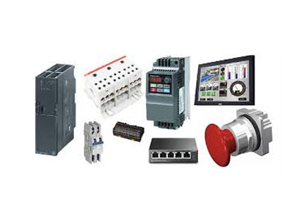
In a control system, a VFD (Variable Frequency Drive) is controlled by a combination of inputs like sensors, PLCs, and operator interfaces. The PLC (Programmable Logic Controller) is typically the main controller, sending commands to the VFD to adjust the motor’s speed and torque.
The VFD takes these commands and modifies the frequency and voltage supplied to the motor. Inputs from sensors, like temperature or pressure sensors, can also influence the VFD’s operation. For example, if the temperature rises, the VFD might slow down the motor to prevent overheating. The operator interface, like a touch screen or buttons, allows manual control and adjustments to the VFD settings. All these components work together to ensure the motor operates efficiently and safely.
The Role of the PLC in Controlling VFDs
A Programmable Logic Controller (PLC) plays a pivotal role in controlling VFDs in industrial systems. The PLC acts as the “brain” of the control system, receiving input signals, processing them based on pre-programmed logic, and sending output commands to the VFD to regulate motor performance. The PLC can directly control the VFD by determining the speed, direction, and torque based on various operational parameters like load conditions, temperature, and speed setpoints.
In typical industrial applications, the PLC communicates with the VFD through discrete digital signals (like start/stop) and analog signals (like speed control). The PLC can also integrate other components in the system, like sensors or operators, to ensure that the VFD adjusts the motor’s behavior according to real-time conditions. For example, if the load on the motor changes, the PLC can send a new command to the VFD to adjust motor speed accordingly, ensuring efficiency and protecting the system from potential overloading.
The PLC provides flexibility in VFD control, allowing users to integrate safety logic, sequence control, and advanced motor protection functions. Additionally, the PLC can monitor motor performance and provide feedback to operators or maintenance teams, which is invaluable for troubleshooting and system optimization.
How Input Signals and Feedback Loops Influence VFD Operation
Input signals and feedback loops are critical components in ensuring precise control of the VFD. These signals can originate from various sources within the control system, including sensors, switches, or human-machine interfaces (HMIs). The input signals provide the VFD with real-time data about the motor’s environment, load conditions, or operational state.
Input Signals:
These signals typically include speed setpoints, start/stop commands, or external operational conditions (e.g., pressure, temperature, or flow rate). For example, a speed signal could be sent from an HMI or a sensor that detects the system’s required speed for optimal performance. The VFD then adjusts the motor’s speed to match this input signal, ensuring that the motor runs efficiently under varying conditions.
Feedback Loops:
A feedback loop is an essential mechanism for closed-loop control. It allows the VFD to receive continuous updates on the motor’s performance and adjust its output to maintain the desired motor characteristics. Feedback can include parameters such as motor speed, voltage, or current. The VFD uses this information to correct any deviations from the desired setpoint, ensuring accurate control.
For example, if the load on the motor increases and the motor speed drops below the setpoint, the feedback system will alert the VFD, prompting it to increase the power output to maintain the required speed. This feedback mechanism allows for more precise control, improved efficiency, and better motor protection by preventing overloading or overheating.
The combination of input signals and feedback loops ensures that VFD operation is dynamic and responsive, adapting to changing conditions in real time and optimizing performance and energy usage.
You May Like to Read
The Impact of Communication Protocols on VFD Control
Communication protocols are the digital languages that allow the PLC, VFD, and other devices within a control system to “talk” to each other. These protocols are essential for data exchange, remote monitoring, and centralized control of VFD systems. Modern VFDs support a range of communication protocols, each suited for specific industrial applications.
Common Communication Protocols:
1. Modbus RTU/TCP:
One of the most widely used communication protocols, Modbus allows for communication between the PLC and VFD, facilitating control and data acquisition. With Modbus, users can remotely monitor motor parameters such as speed, current, and temperature, and adjust settings without needing to be physically present at the control panel.
2. Profibus/Profinet:
These are high-speed protocols used for more complex and real-time control systems. They allow for faster communication between devices and are commonly used in large-scale industrial automation systems. Profibus is often used in SCADA systems, while Profinet provides more flexibility and scalability, allowing for distributed control of multiple VFDs.
3. Ethernet/IP:
Ethernet/IP is gaining popularity in industries that require high-speed communication and integration with IT systems. This protocol allows devices to communicate over Ethernet networks, providing enhanced flexibility for remote monitoring and control.
Communication protocols allow the VFD to be part of a larger automation system, enabling seamless integration with sensors, HMIs, and other machines. The use of these protocols enhances system performance, enables real-time diagnostics, and allows for optimized control of motors in complex applications.
How External Controllers Interface with VFDs in Complex Systems
In more complex control systems, external controllers can provide additional control capabilities beyond what the PLC alone can manage. These external controllers might include specialized motor controllers, remote control panels, or centralized process controllers that interact with the VFD to achieve specific operational goals.
External Motor Controllers:
In some systems, external motor controllers can be used to set parameters like torque limits, acceleration/deceleration ramps, and motor protection. These controllers may be directly wired to the VFD or connected via communication protocols. By offloading certain control functions to external controllers, the PLC can focus on higher-level tasks, improving the efficiency of the entire control system.
Remote Control Panels:
Remote control panels or HMIs allow operators to interact with the VFD from a distance. These panels can send control signals to adjust motor speed or direction, and they can display real-time performance data such as motor speed, voltage, or current. Operators can monitor the system’s performance and make changes to setpoints without needing to be at the main control panel, improving accessibility and operational flexibility.
Integration with Distributed Control Systems (DCS):
In large facilities, VFDs are often part of a distributed control system (DCS) that manages multiple devices and processes. The DCS sends control signals to the VFDs and receives feedback, allowing for centralized monitoring and control. This integration allows for more efficient operation, better coordination between systems, and improved fault diagnosis.
The Function of Speed and Torque Control in VFD Regulation
Speed and torque control are two of the most critical aspects of VFD regulation, allowing for precise management of motor performance in various industrial applications. These controls ensure that motors operate within their optimal parameters, maximizing efficiency while minimizing wear and tear on the system.
Speed Control:
Speed control allows the VFD to adjust the motor’s speed to meet the demands of a particular task. For instance, in a pump system, the VFD can adjust the motor speed based on the required flow rate, optimizing energy usage. Speed control is typically achieved by varying the frequency of the AC voltage supplied to the motor. A higher frequency results in faster motor speeds, while a lower frequency slows down the motor.
Torque Control:
Torque control regulates the amount of force the motor generates to drive a load. In applications where precise torque control is required, such as in cranes or hoists, the VFD adjusts the motor’s current to maintain the required torque without exceeding the motor’s capacity. Torque control can be achieved using both open-loop and closed-loop methods, with closed-loop control providing greater accuracy by continuously adjusting the current based on feedback from the system.
Together, speed and torque control provide the flexibility to optimize motor performance for different operational conditions, improving both energy efficiency and the longevity of the motor.
Conclusion
To sum up, the control of VFDs in industrial systems is a complex yet essential process involving several key components. PLCs serve as the central controller, managing inputs, outputs, and communication with the VFD. Feedback loops and input signals ensure precise regulation of motor performance, while communication protocols and external controllers enable seamless integration within larger control systems. By understanding how these various control mechanisms interact, engineers can optimize VFD performance, improve energy efficiency, and enhance the overall reliability of motor-driven systems in industrial environments.