Key Takeaway
A VFD, consists of three essential components: a Rectifier, a DC link, and an Inverter. The rectifier converts incoming AC power to DC. This DC power is then smoothed and stored in the DC link, acting as an intermediary energy storage. The inverter then converts the DC power back to AC, but with variable frequency and voltage according to the motor’s speed requirements. Together, these components enable precise control over motor speed and torque, crucial for optimizing energy efficiency and operational performance in industrial applications. Understanding these parts is fundamental for engineers designing and implementing VFD systems to meet specific operational needs effectively.
Overview of VFD Components
Variable Frequency Drives (VFDs) are essential in modern industrial applications, offering precise control over motor speed and torque. For a newly joined engineer, understanding the main parts of a VFD is crucial. A VFD comprises several key components: the rectifier, the DC bus, the inverter, and control and interface components. Each part plays a specific role in converting and controlling electrical power to achieve the desired motor performance.

The Rectifier Section
The rectifier section serves as the initial stage in a VFD, crucially converting incoming AC power into DC power essential for further processing. Typically employing diodes or silicon-controlled rectifiers (SCRs), this section ensures the AC power is transformed into a unidirectional flow of DC. Diodes facilitate this conversion by allowing current to flow in one direction only, ensuring a steady DC output. In contrast, SCRs offer more precise control over the rectification process, making them suitable for applications demanding exacting operational parameters.
The efficiency and quality of the rectifier significantly influence the overall performance of the VFD. Understanding this component is pivotal for engineers, as it directly impacts the VFD’s reliability and efficiency in industrial settings. By grasping the role of the rectifier section and its technology, engineers can optimize VFD performance, ensuring seamless integration and operation within diverse industrial applications worldwide. This foundational knowledge empowers engineers to make informed decisions and maintain the operational integrity of VFD systems across various industrial environments.
You May Like to Read
The DC Bus in VFDs: Ensuring Power Stability
Once AC power is converted to DC, it enters the DC bus, a critical component in Variable Frequency Drives (VFDs). The DC bus functions as a reservoir where capacitors smooth out the rectified DC voltage, eliminating ripples and ensuring a consistent, stable DC supply. This stability is paramount for the inverter’s operation, as it directly impacts the quality of power supplied to the motor.
A well-designed DC bus plays a vital role in minimizing electrical noise and voltage fluctuations, which can otherwise affect the VFD’s efficiency and reliability. Engineers must grasp the significance of maintaining power stability in VFDs, as it enhances overall system performance and longevity. Understanding the DC bus’s function empowers engineers to optimize VFD setups for various industrial applications, ensuring smooth operations and reducing the risk of electrical disturbances.
The Inverter Section
The inverter section of a VFD is where the direct current (DC) power is converted back to alternating current (AC) power. This conversion is done at a variable frequency and voltage, allowing for precise control over the motor’s speed and torque.
To achieve this, the inverter section uses insulated-gate bipolar transistors (IGBTs). These components switch the DC power on and off rapidly, creating a pulse-width modulated (PWM) signal. This PWM signal effectively mimics an AC waveform, which the motor can use.
By adjusting the frequency and width of these pulses, the VFD can precisely control motor speed and torque. This control is crucial for applications requiring variable speeds and high efficiency.
The efficiency and precision of the inverter section directly impact the motor’s performance. Therefore, engineers must focus on optimizing this part of the VFD. Properly managing the inverter section ensures that the motor operates smoothly, efficiently, and reliably.
Control and Interface Components
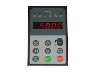
Control and interface components are the brains of a VFD, essential for setting parameters, monitoring performance, and enabling communication with other systems. These components include microcontrollers, sensors, and communication interfaces like Modbus or Ethernet. The control system processes input signals, executes control algorithms, and adjusts the inverter’s output to match the motor’s requirements.
Understanding these components is crucial for engineers. Microcontrollers handle the processing tasks, sensors monitor various parameters, and communication interfaces facilitate interaction with external systems. This knowledge helps engineers troubleshoot issues effectively and optimize VFD performance, ensuring the motor operates efficiently and safely.
Familiarity with control and interface components allows engineers to enhance VFD functionality, leading to improved operational efficiency and reliability in industrial applications.
Conclusion
In conclusion, grasping the main components of a VFD – the rectifier, DC bus, inverter, and control and interface components – is vital for any engineer in the industrial sector. Each part plays a distinct role in converting and controlling electrical power, ultimately allowing precise motor control. By understanding these components, engineers can effectively troubleshoot, optimize, and maintain VFD systems, ensuring efficient and reliable motor operation in various industrial applications. Remember, a well-maintained VFD not only enhances performance but also extends the lifespan of both the drive and the motor it controls.
