Key Takeaway
The AC and DC symbols on a multimeter indicate the type of current being measured. AC voltage is represented by “V~” (with a tilde), and DC voltage is represented by “V-” (with a dash).
These symbols help you select the correct setting for testing different types of voltage in circuits, batteries, or devices.
Introduction to AC and DC Symbols on Multimeters
AC and DC symbols on a multimeter differentiate between alternating and direct current measurement modes. The AC symbol is represented by “~,” while DC is shown as a straight line with a dashed line underneath.
These symbols guide users in selecting the appropriate mode for their task. For instance, choose AC mode for household wiring and DC mode for testing batteries. Properly using these settings ensures accurate measurements and protects the device from damage.

Identifying the AC and DC Symbols on Different Models
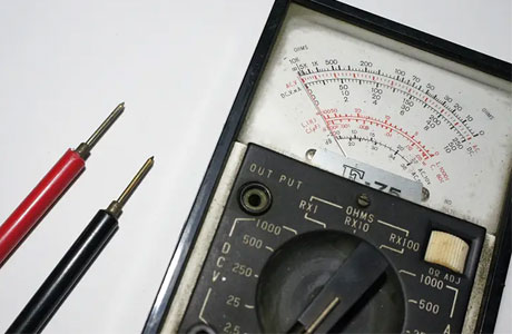
Multimeters typically include different symbols to indicate whether you’re measuring AC or DC voltage, current, or resistance. Recognizing these symbols is key to correctly using the multimeter and obtaining accurate measurements.
For DC voltage, the symbol is usually a “V” followed by a straight line (─) beneath it. This symbol indicates that the multimeter is set to measure direct current, which flows in a single direction. DC voltage measurements are common when testing power supplies, batteries, or low-voltage devices.
For AC voltage, the symbol is often a “V” with a tilde (~) next to it. The tilde indicates alternating current, where the flow of electricity changes direction periodically. AC voltage measurements are used for testing standard household electrical outlets, industrial equipment, and power lines.
Some multimeters have separate settings for AC and DC voltage, while others use a combined setting with an option to switch between the two. It’s crucial to select the correct setting to ensure accurate readings, as measuring AC voltage on a DC circuit (or vice versa) can lead to incorrect results or even damage the multimeter.
You May Like to Read
Applications for AC and DC Voltage Measurement
AC and DC voltage measurements have diverse applications in both industrial and residential settings. Knowing when to use each mode is key to effective diagnostics.
AC Voltage Applications:
Power Outlets: Testing wall sockets and verifying supply voltage.
Industrial Equipment: Monitoring large-scale machinery powered by alternating current.
Transformers and Generators: Ensuring these devices function within specified voltage ranges.
DC Voltage Applications:
Battery Testing: Measuring charge levels in automotive and household batteries.
Solar Panels: Verifying the output voltage of renewable energy systems.
Electronic Devices: Diagnosing faults in devices powered by DC circuits.
For an engineer, distinguishing between these applications ensures the multimeter is used effectively. Testing AC voltage when DC mode is required—or vice versa—can lead to faulty diagnostics, so always confirm the type of current in your circuit beforehand.
Tips for Efficient AC/DC Testing in Circuits
AC/DC testing is a vital task in electrical work, from troubleshooting household wiring to diagnosing complex industrial systems. Efficiently testing both AC and DC circuits requires understanding the behavior of these two types of electrical currents and knowing how to adjust your multimeter for accurate readings. The first step in efficient testing is to properly identify whether the circuit you’re working with is AC or DC. DC voltage is constant and flows in one direction, while AC voltage alternates direction periodically.
When working with DC circuits, start by setting your multimeter to the V (DC) setting, which typically shows a straight line or a dashed line next to the V symbol. This is commonly used for devices like batteries, power supplies, and low-voltage electronics. For AC circuits, use the V~ setting, which measures alternating current that fluctuates sinusoidally. Household power, industrial equipment, and appliances all use AC power, so it’s crucial to select the V~ setting when testing outlets or systems powered by AC.
Another important tip for efficient AC/DC testing is to use an auto-ranging multimeter. This feature allows the multimeter to automatically detect the appropriate range for the voltage or current you’re testing, simplifying the process and reducing the chances of human error. In manual mode, ensure that the range you set matches the expected voltage level in the circuit. Also, be mindful of the probes’ positioning when taking measurements to avoid inaccurate readings or electrical shock.
Avoiding Errors in AC/DC Settings
When using a multimeter for testing circuits, ensuring the correct AC or DC setting is crucial for obtaining accurate measurements. One of the main mistakes that users make is leaving the multimeter on the wrong setting, such as trying to measure AC voltage in a DC circuit or measuring DC voltage in an AC circuit. This can lead to incorrect readings or even damage the multimeter.
To avoid errors in AC/DC settings, always double-check the setting before performing a measurement. Look for the specific “V~” symbol for AC voltage and “V-” for DC voltage on your multimeter. Additionally, some multimeters have an auto-range function, which helps simplify the process and automatically selects the appropriate setting for the measurement. For more advanced multimeters, users can also choose between different AC waveform types (sine, square, etc.) if needed. This will ensure the most accurate reading of voltage and prevent any confusion when working with mixed AC and DC circuits
Conclusion
The AC symbol (V~) represents alternating current, while the DC symbol (V) represents direct current. These symbols guide users in choosing the appropriate setting for their measurements.
Understanding these symbols is fundamental for anyone using a multimeter, ensuring safe and accurate measurements in any application.
