Key Takeaway
To check whether a voltage is AC or DC, set the multimeter to the voltage measurement mode. For AC, select the AC voltage (V~) setting, and for DC, choose the DC voltage (V-) setting.
Connect the probes to the circuit or battery, and the multimeter will display the voltage. The display will show a negative sign for DC voltages and a normal reading for AC.
Differentiating Between AC and DC in Multimeters
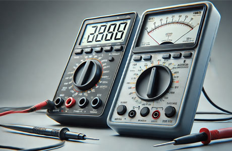
AC (Alternating Current) and DC (Direct Current) are two types of electrical currents, and multimeters can measure both. AC current periodically reverses direction, as seen in power from outlets, while DC current flows in one direction, as found in batteries.
On a multimeter, AC is represented by a “~” symbol, while DC is represented by a straight line with a dashed line underneath. The ability to measure both types is essential for troubleshooting different electrical systems. For instance, measuring AC voltage is necessary for checking wall outlets or appliances, while DC voltage is used to test batteries or electronic circuits.
Understanding the difference between AC and DC, and knowing how to measure each with a multimeter, is a fundamental skill for anyone working with electrical or electronic systems.
Steps to Identify AC Voltage Using a Multimeter
To measure AC voltage accurately with a multimeter, follow these steps:
Set the Multimeter to AC Mode: Begin by setting your multimeter to the AC voltage (V~) mode. Most digital multimeters will display the symbol “V~” for AC voltage, while analog versions may have an AC symbol or different labeling. Ensure that the multimeter is set to the appropriate voltage range for your system. If you’re unsure, it’s best to start with the highest voltage setting.
Connect the Probes: Insert the black probe into the common terminal (COM) and the red probe into the terminal labeled for voltage measurement (typically marked with “V”). The black probe should be connected to the ground or neutral point, while the red probe is connected to the live or phase wire.
Take the Measurement: Place the probes on the circuit, with the black probe on the neutral side and the red probe on the live side. Read the voltage display on the multimeter. AC voltage will typically fluctuate, showing a sinusoidal waveform on an oscilloscope if available, but on the multimeter, it will show as a stable reading of the voltage.
Record and Interpret the Measurement: Once you have the reading, compare it to the expected AC voltage values for the device or system you are testing. If you are testing a standard outlet, it should read close to 120V or 230V, depending on your region.
You May Like to Read
Steps to Identify DC Voltage Using a Multimeter
Identifying DC voltage using a multimeter is a straightforward process, but it’s important to follow these steps carefully to ensure accuracy:
Set the Multimeter to DC Mode: Set the multimeter to measure DC voltage by turning the dial to the “V-” symbol, which represents DC voltage. Some multimeters might label it as “DCV” or use a straight line with a dotted line underneath it. Again, choose the appropriate voltage range for your circuit.
Insert the Probes: Place the black probe into the common terminal (COM) and the red probe into the voltage terminal (V). For DC voltage, the polarity of the probes matters. The black probe should be connected to the negative terminal (ground) and the red probe should be connected to the positive terminal of the circuit.
Place the Probes on the Circuit: Position the black probe on the negative side (ground) and the red probe on the positive side of the circuit. If you are testing a power supply or a battery, connect the probes directly to the battery terminals or power source.
Take the Measurement: Read the voltage display on the multimeter. The value should be a steady number without fluctuations, as DC voltage doesn’t vary over time. A typical DC voltage in a battery-powered circuit might range from 1.5V (for small batteries) to 12V or higher for larger systems.
Interpret the Results: Compare the multimeter reading with the known voltage for the device or system you are testing. A discrepancy could indicate a problem with the power source, such as a drained battery or malfunctioning power supply.
By following these steps, you will be able to measure DC voltage accurately in your circuits.
Importance of Correct AC/DC Settings in Measurements
Correctly setting the AC/DC mode on a multimeter is essential for accurate measurements. AC (alternating current) and DC (direct current) are different types of electrical current, and measuring them with the wrong setting can lead to inaccurate readings or even damage the multimeter. AC current varies sinusoidally, whereas DC current flows in a constant direction, making their measurements distinct from each other.
When testing AC circuits, the multimeter must be set to the AC voltage or current mode, typically indicated with a sine wave symbol. This ensures that the multimeter accurately measures the varying nature of AC signals. On the other hand, DC circuits require the multimeter to be set to the DC mode, often marked with a straight line symbol. Incorrectly setting the multimeter can cause it to give false readings or display an error message, especially when testing circuits with specific characteristics.
Accurately setting the multimeter to the correct mode also protects the device from potential damage. For instance, if you attempt to measure AC voltage with the multimeter set to DC mode, the multimeter may not function correctly and could be damaged due to the mismatch. By always ensuring the multimeter is set to the proper AC or DC mode, users can guarantee reliable readings and preserve the longevity of their multimeter.
Key Applications for AC and DC Testing in Circuits
AC and DC testing are fundamental to multimeter functionality, and understanding their respective applications is key to accurate measurements. AC voltage testing is crucial in circuits powered by alternating current, such as household electrical systems or industrial machines. It helps verify voltage levels, detect irregularities, and ensure the equipment operates safely. On the other hand, DC testing is vital for circuits powered by direct current, like batteries and low-voltage electronics.
AC testing is commonly used for higher voltage systems like motors, transformers, and household appliances, whereas DC testing is more relevant for testing electronic components such as resistors, capacitors, and integrated circuits. Properly selecting the correct setting (AC or DC) on the multimeter is essential for accurate results. For instance, testing a DC circuit on an AC setting can result in misleading readings. Always check the type of circuit you are testing and set the multimeter accordingly.
Conclusion
To check AC or DC, set the multimeter to the appropriate mode (V~ for AC, V for DC), connect the probes, and observe the reading. The correct setting ensures accurate measurements and prevents damage to the multimeter.
Understanding how to differentiate between AC and DC measurements is essential for effectively diagnosing and repairing electrical systems.