Key Takeaway
The principle of a multimeter is based on converting electrical properties, such as voltage, current, and resistance, into readable signals. This is done using internal circuits that process the electrical signals and display the results.
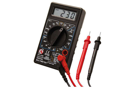
In digital multimeters, the readings are shown on an LCD screen, while in analog models, a needle moves across a scale. The device’s sensors measure the electrical quantity, providing accurate results for diagnostics and troubleshooting.
Understanding the Working Mechanism of Multimeters
Multimeters operate by using internal circuits to measure specific electrical properties such as voltage, current, and resistance. When you connect the test leads to a circuit, the multimeter interprets electrical signals based on the selected mode. For voltage, the device measures the potential difference between two points, while for resistance, it sends a small current through the circuit and calculates resistance based on the voltage drop.
Advanced multimeters include features like auto-ranging, which automatically selects the correct range for measurements, and microprocessors, which enhance accuracy. Analog models use a needle that moves across a scale, while digital multimeters display precise numerical values on a screen.
The working mechanism also includes safety features like overload protection to prevent damage during testing. Understanding how a multimeter works ensures you use it effectively and safely, whether diagnosing a blown fuse, testing a circuit, or measuring electrical parameters in more complex systems. This foundational knowledge is essential for troubleshooting and maintaining electrical systems in any setting.
How Multimeters Measure Voltage, Current, and Resistance
Multimeters are versatile devices used to measure electrical properties such as voltage, current, and resistance, essential for diagnosing electrical systems. These measurements are performed using different settings on the multimeter, and each type of measurement is crucial in determining the functionality and safety of electrical components.
Voltage Measurement: To measure voltage, the multimeter is set to either the DC or AC voltage setting, depending on the type of voltage being tested. Voltage is measured by connecting the multimeter probes across the component or circuit, with the multimeter acting as a high-impedance device to avoid drawing current. The multimeter then displays the potential difference between the two points in volts (V).
Current Measurement: To measure current, the multimeter needs to be placed in series with the component or circuit. This allows the current to flow through the multimeter so it can measure how much electricity is passing through. Current is typically measured in amperes (A), and it is important to set the multimeter to the correct range to avoid damaging the device.
Resistance Measurement: When measuring resistance, the multimeter is set to the resistance mode (Ω), and the probes are connected across the component. The multimeter sends a small current through the resistor, and based on the opposition to the flow, it calculates the resistance in ohms (Ω). This measurement helps in testing whether components like resistors are functioning as expected.
By using these modes, multimeters provide critical insight into the health and functionality of electrical circuits.
You May Like to Read
The Importance of Internal Circuitry in Multimeter Functionality
The internal circuitry of a multimeter is crucial in ensuring that it delivers accurate and reliable measurements. At its core, a multimeter uses a combination of resistors, capacitors, diodes, and other electronic components to function correctly. These internal components interact to measure electrical properties such as voltage, current, and resistance.
The voltage measurement circuit, for instance, involves a voltage divider that reduces the voltage being measured to a level that is safe and detectable by the multimeter. This allows the multimeter to display an accurate reading on the screen. In the case of current measurement, the multimeter uses a shunt resistor to divert a portion of the current to be measured. By calculating the voltage drop across this resistor, the multimeter can compute the current flowing through the circuit.
Additionally, the internal analog-to-digital converter (ADC) is essential for translating the analog signals into digital readings. This converter processes the voltage, current, or resistance values and displays them on the multimeter’s digital display. The accuracy of the ADC directly influences the precision of the readings.
Finally, high-quality internal shielding is critical to prevent interference from external electromagnetic signals, which could distort the readings. A well-designed multimeter ensures that its internal circuitry is shielded from external noise, enabling accurate readings even in electrically noisy environments.
The internal circuitry of a multimeter thus directly impacts its performance, reliability, and the overall user experience. When selecting a multimeter, the quality and design of the internal components are just as important as the external features and functionality.
Role of Analog-to-Digital Conversion in Digital Multimeters
The core functionality of a digital multimeter (DMM) relies on analog-to-digital conversion (ADC), a process that allows the multimeter to provide precise, numerical measurements. Analog signals, such as voltage or current, are continuous in nature, meaning they can take on any value within a specific range. However, to display a readable value, the multimeter must convert these continuous signals into a discrete digital format. This is where the ADC comes into play. It samples the continuous analog signal at regular intervals, and then converts each sample into a binary value that can be interpreted by the device’s microprocessor.
The accuracy and precision of a digital multimeter are largely determined by the quality of the ADC used. Higher-quality ADCs can sample signals more frequently and with greater resolution, resulting in more precise measurements. In practical terms, this means that multimeters with high-resolution ADCs are capable of measuring smaller changes in electrical properties, which is crucial when testing sensitive components or systems. The digital display on the multimeter presents these readings in a clear, easy-to-understand format, eliminating the need for interpreting needle movements, as in the case of analog models.
Moreover, the ADC process in digital multimeters improves safety and usability. Digital readings are less prone to user interpretation errors than analog displays, reducing the risk of incorrect measurements. Furthermore, because of their ability to convert analog signals into accurate, stable digital outputs, digital multimeters have become the industry standard for most electrical testing and troubleshooting tasks.
Common Principles Shared Between Analog and Digital Models
Although analog and digital multimeters operate on different principles, they share several core functionalities and principles that make them both valuable tools for electrical testing. One of the fundamental principles common to both types of multimeters is their ability to measure three key electrical parameters: voltage, current, and resistance. Whether analog or digital, both types of meters can be used to assess these parameters in circuits, helping technicians troubleshoot issues, confirm electrical values, and ensure the proper operation of electrical systems.
Both analog and digital multimeters also rely on Ohm’s Law, which states that voltage equals current multiplied by resistance (V = IR). This relationship is essential for accurate measurements of all three parameters, and it is applied in both analog and digital circuits. In an analog multimeter, the current flowing through the meter’s internal components causes a needle to deflect, providing a visual representation of the measured value. In contrast, digital multimeters convert the measured signal into a digital format, providing a numerical reading on a screen.
Despite the difference in display technology, both types of meters follow the same underlying electrical principles. Another principle shared between analog and digital multimeters is their ability to test continuity, ensuring that electrical paths are complete and uninterrupted. Both models emit an audible beep when there is continuity, making them valuable tools for identifying broken wires or faulty connections in a circuit. While digital meters may provide more precise readings, analog meters are often preferred for their simplicity in providing quick feedback on continuity.
Both analog and digital multimeters are also versatile tools that can measure additional electrical parameters, such as capacitance, temperature, and frequency. In essence, although the technologies behind analog and digital multimeters differ, their fundamental principles remain the same—making them both indispensable tools for electrical professionals. |
Conclusion
The principle of a multimeter lies in its ability to combine multiple measurement functions into one device. It operates by using internal circuitry that measures electrical properties such as voltage, current, and resistance. Multimeters are designed with various settings to switch between different modes (voltage, current, resistance), and each mode uses distinct principles to obtain measurements. In voltage mode, the multimeter measures the difference in electrical potential between two points. In current mode, it measures the flow of electrons, and in resistance mode, it measures the opposition to current flow.
Digital multimeters, in particular, use an analog-to-digital converter (ADC) to convert the electrical signal into a readable digital value. This is more precise than the analog system, where the measurement is interpreted by the movement of a needle on a scale. The multimeter’s internal components work together to ensure that readings are accurate and that users can switch between different measurement modes efficiently.